

LNG terminals and offshore facilities are the hardest places to run a piping design workflow. The layouts are dense, the specifications are tight, the lines are large and sometimes cryogenic, and the schedule rarely has slack. In an Octave Forte 3D (formerly Hexagon Smart 3D) project, these conditions push the manual detailing workload up at exactly the point where the team has the least room to absorb it.
This article looks at what makes LNG and offshore piping different, how those differences change the manual detailing workflow, and where native automation has the most room to help. It is a vertical guide: the general workflow is the same as onshore plants, but the density and the consequences of error are not.
1. Why LNG and Offshore Piping Is Different
The engineering workflow for an LNG terminal or an offshore facility follows the same phases as an onshore plant: conceptual design, FEED, detailed engineering, procurement, construction, and commissioning. The difference lies in the conditions inside those phases.
Offshore and LNG work combines four pressures:
- Space is constrained. Offshore facilities operate within highly constrained layouts, so design integration between piping, structure, and mechanical disciplines becomes one of the biggest execution challenges (Rishabh Engineering, FPSO design).
- Lines are large and sometimes cryogenic. Some refrigerant piping can reach 1,500 mm in diameter before insulation, and cryogenic pipe supports and large-bore stainless steel involve different fabrication practices from traditional FPSO work (Offshore Magazine, early FLNG projects).
- Motion and deflection matter. Equipment supports and piping flexibility must account for vessel motion and hull deflection, including hogging and sagging (Offshore Magazine).
- Errors are costlier. A support that does not match the drawing on a constrained offshore module, or on a dense LNG pipe rack, can delay steel erection by weeks (Matterport, LNG expansion framework).
The conclusion for piping design is that the number of decisions per square meter goes up, and the cost of each wrong one goes up with it.
2. Density: More Supports in Less Space
Density is the first place the workload grows. In a dense LNG pipe rack or an offshore module, a single run of pipe can require many supports within a short distance, and each support must be placed, attached, and detailed.
The manual support workflow handles each support position in sequence. The per-unit effort looks small. Multiplied across the support count of a dense module, it becomes the dominant share of the detailing schedule.
Shinsei Vietnam’s benchmark for the manual support lifecycle on one representative support, from assembly input through control point detailing, is about 39 minutes, reduced to about 4.6 minutes with native automation (illustrative composite, WP7). On a dense project, support count is the multiplier that determines whether that difference matters. On an LNG or offshore package with a high support count, it matters a great deal.
| Manual Task | Benchmark | With Automation |
| Support attachment to isometrics (6 positions) | 12.0 min / 30 steps | 0.5 min / 3 steps |
| Control point detailing (12 CPs per drawing) | 24.0 min / 60 steps | 1.0 min / 3 steps |
[Internal link: “Pipe Support Design Automation in Octave Forte 3D — A Complete Technical Guide”] The full six-stage support lifecycle with benchmarks for each stage.
3. Cryogenic and Large-Bore Lines Add Support Complexity
LNG liquefaction introduces lines that are both large and cold. Refrigerant piping can reach very large diameters, and cryogenic lines bring pipe stress, support design, and insulation requirements that a standard hydrocarbon line does not.
These lines carry more support-related decisions per pipe: support type, insulation interface, thermal contraction allowance, and attachment detail. Each decision is a source of potential error if it is carried through manually across many drawings. The drawing that shows the support must show the right type, the right position, and the right control points, for a line whose behavior changes with temperature.
Two practical consequences for the workflow:
- Drawing consistency matters more. A cryogenic support drawing that is slightly inconsistent with its neighbors creates confusion on a fabrication shop floor, where the spool is built from that drawing.
- Attachment completeness matters more. A skipped support on a large-bore cryogenic line is an expensive miss, because the omitted support is typically found at fit-up.
Batch-processed attachment and rule-based control points address both consequences because the output follows the same rules on every drawing, regardless of line size or service.
4. Motion, Hull Deflection, and Flexibility
Offshore piping must be designed for conditions that onshore plants do not face. Vessel motion, hull deflection, and the flexibility of lines connected to equipment on a moving or flexing structure all change the support design.
These conditions show up in the workflow as more support revisions. When the stress analysis or the structural team changes a support position, every affected isometric and support drawing must be updated. On a manual workflow, each update is a fresh round of attachment and control point work for the affected drawings.
This is where automation helps most in revision cycles. A batch that can be re-run across the affected drawing set turns a revision from a multi-day manual effort into a bounded task, and it reduces the chance that one affected drawing is missed.
[Internal link: “Plant Design Workflow — Where Piping Consumes 30–50% of Detailed Engineering”] Why revision cycles in detailed engineering concentrate effort on piping.
5. Where the Manual Workflow Breaks Down in These Projects
Four points of breakdown recur on dense, complex piping projects. Each is a manual step that becomes harder as density and complexity rise.
Support attachment across many pipelines. The default workflow handles support positions pipeline by pipeline. On a dense rack with many lines, the sequence is long and the chance of a skipped position rises.
Control point entry at volume. Adding 12 control points per drawing across hundreds of support drawings is the step where fatigue-driven errors are most likely, and where a single misplaced dimension can lead to a fit-up failure on a large line.
Label and scale consistency across a large package. A package of several hundred drawings prepared by many drafters shows drift in label placement and scale choice. Reviewers catch it, and rework follows.
Revision handling. Each change from stress analysis, structure, or vessel motion requires the affected drawings to be updated. Manual revision cycles are where the schedule usually slips.
These points tie directly to the drawing-error categories in the QA/QC Prevention Report (WP5), which covers each one in detail.
6. Where Native Automation Has the Most Room to Help
Automation does not change the physics of an LNG or offshore design. It changes the manual layer on top of it. Three applications have the most room on these projects.
Batch support attachment for dense racks. InputSupportAttach processes multiple support positions across multiple pipelines in one execution. On a dense rack, the sequential constraint of the default method is removed, and no position needs to be tracked by hand.
Rule-based control points for large-bore and cryogenic drawings. AddControlPointToSupport places the 12 standard CPs across a batch of drawings from the support geometry and the active piping specification, so the same rules apply to a 6-inch line and a 60-inch refrigerant header.
Consistent labels and scales for large packages. AlignLabel and DwgSupportScale apply one configuration file across the package. This matters most when several drafters work on a package of hundreds of drawings.
| Project Condition | Where Automation Helps |
| High support count in dense racks | Batch attachment removes the sequential bottleneck |
| Large-bore and cryogenic lines | Rule-based CPs apply the same logic across line sizes |
| Large drawing packages | Configuration-driven labels and scales keep output consistent |
| Frequent revision cycles | Batch re-run reduces the manual cost of each change |
Benchmark figures for these tasks come from the Shinsei Vietnam measurements referenced throughout this series. Actual results on an LNG or offshore project depend on support count, drawing standard, and model conditions, so the pilot is the place to confirm them.
7. Brownfield Work and Verified Existing Conditions
Many LNG projects are expansions at existing terminals. Brownfield work adds a different risk: the design must fit an existing layout, and any mismatch between drawings and the physical site becomes a field conflict.
Industry guidance on LNG expansion stresses verifying existing conditions before detailed design, and using accurate as-built data where it exists. Point clouds and dimensionally accurate models can supply that data (Matterport, LNG expansion framework).
For the piping workflow, the implication is this: a support drawing is only as good as the site data behind it. Automation makes the drawing output consistent, but it cannot make a wrong dimension from the site correct. Verify the existing conditions first, then automate the output.
8. A Starting Plan for Vertical Projects
For an LNG or offshore project considering automation, a practical sequence starts with the work that carries the highest support and drawing volume:
- Measure the baseline on a dense rack or module package. Time one representative package manually, including support attachment, control points, and labels, and count the supports.
- Pilot batch support attachment and control points on that package, since they address the largest per-unit costs.
- Confirm consistency on a large-bore or cryogenic subset, checking that the output matches the drawing standard for those lines.
- Extend to labels and scales across the full package once the first two results are confirmed.
- Apply the pattern to revisions from stress analysis and structural changes.
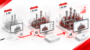
The rollout structure should follow the 90-day approach in Blog 11, with the pilot scoped to a single dense package.
[Internal link: “The First 90 Days: A Realistic Implementation Timeline for Forte 3D Automation”] The week-by-week rollout structure to apply to a vertical project.
9. References and Further Reading
Offshore and LNG Piping Context
- Early FLNG Projects Deal With Technical and Execution Challenges — Offshore Magazine: Covers refrigerant piping diameters, cryogenic pipe supports, and large-bore stainless steel fabrication.
- FPSO Design Engineering for EPC & PMC Teams — Rishabh Engineering: Describes piping, structural, and mechanical interface management in constrained offshore layouts.
- LNG Export Growth: How to Control Infrastructure Expansion — Matterport: Brownfield verification practice and the use of dimensionally accurate data in LNG expansion design.
- What Is EPC in Oil & Gas? Top 10 EPC Companies in 2026 — Blackridge Research: Overview of EPC contract scope for LNG terminals and offshore platforms.
10. FAQ
Q1. Do LNG and offshore projects need a different automation approach from onshore plants? The tools are the same. The priorities shift. Dense racks and large-bore cryogenic lines push support attachment and control point work higher on the list, and revision cycles from motion and structural changes become a bigger share of the workload.
Q2. Is Octave Forte 3D used on offshore and FPSO projects? Forte 3D is used across oil and gas and LNG projects, and EPC firms choose their platform by client mandate and project type. Confirm the platform requirement with the client before planning the workflow.
Q3. Does automation help with cryogenic supports specifically? It helps with consistency and completeness, meaning every drawing follows the same rules and no support position is skipped. It does not replace cryogenic engineering judgment on support type, insulation interface, or contraction allowance, which remain the engineer’s responsibility.
Q4. How should revision cycles from stress analysis be handled? Batch-process the affected drawing set after each approved change, and record which drawings were re-run. Manual revision is where drawings are most often missed.
Q5. What is the best pilot package for a dense LNG or offshore project? Choose a package with a high support count and a clear drawing standard, ideally one that is not on the immediate critical path, so the pilot can run without threatening delivery. Measure the baseline first.
Shinsei Vietnam is a specialist Octave Forte 3D automation partner, part of Tatsusei Giken. Our 16-macro suite is built exclusively for Octave Forte 3D (formerly Hexagon Smart 3D) using native API integration. We serve EPC firms globally on oil and gas, petrochemical, LNG, and industrial plant projects.